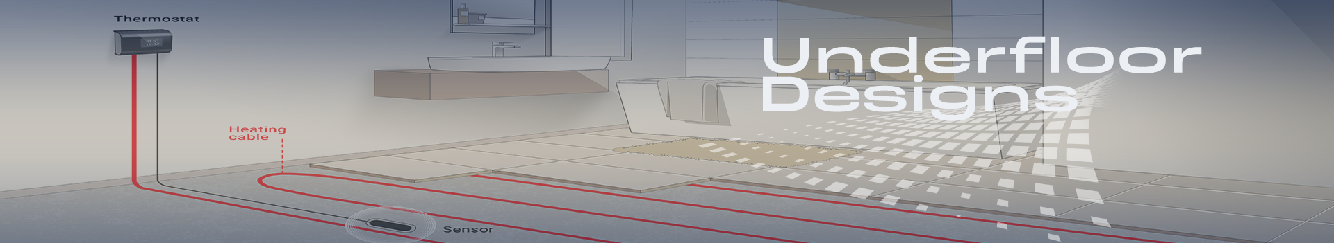

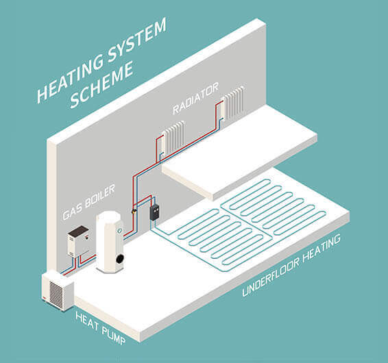
Underfloor Designs
Underfloor design defines the management of rising heat in your room. Depending upon room size, space, and shape, planning for such installation may need to take place before any physical assembly of pipework can begin. The designs of the heating system are drafted based on room’s unique size, shape, and feature for proper functioning and installation.
Importance of UFH
Proper Underfloor layout design is essential to make sure that the system being installed is sufficient for the area that is being heated. Incorrect design can lead to a heating system that is under-specified, meaning that the desired heat output in each area is not achieved. Rectifying mistakes caused by design error after the installation has taken place will be costly and inconvenient, to say the least. These points to the importance of making sure designs are accurate and facilitate the correctly-sized system being installed to the area. It’s important to never miss a detail when it comes to UFH design. A good design will always be bespoke to the project, taking various factors into account to create an efficient solution that effectively heats the property even when it’s a freezing outside. What you might not know is that there’s a lot more to UFH design than just the tube drawing. We’re taking a look at all the factors that make up a quality system design.
Our UFH Drafting Designs
In this way, you can come away with a bespoke and unique Underfloor heating installation that both complements and benefits your room and anyone likely to be in it. The countries around the globe use this for maintaining heat in their residential & commercial areas.
Quick Calculation
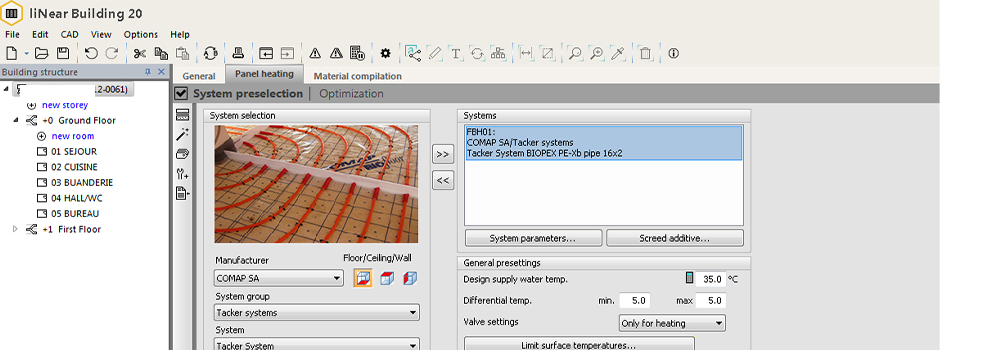
InfoTech provides Quick calculation and Heat Load calculation facility in accordance with the drafting services. The standards used for Heat load is based on DIN EN 12831. We use Excel and liNear software for heat load calculation purpose. The version of liNear we are using at present is liNear Building 20 with AutoCAD 2016.
The liNear heat load consists of Standard heat load calculation according to the extensive calculation procedure according to EN 12 831 with the specifications in the European supplementary sheet to EN 12 831.
We might need following information for carrying out heat load calculation: :
- Location of the building
- Height above sea-level (if known)
- Type of building (1 family house etc.)
- Building length (in meters)
- Building width (in meters)
- Building area (in square meters)
- Building height (in meters)
- Building volume ( in cubic meters)
- Length of ground (in meters)
- Width of ground (in meters)
- Ground water depth (in meters)
- Depth of bottom plate (in meters)
- Standard outside temperature (in degree Celsius)
- Room temperature (in degree Celsius)
We can provide the customer with the Tender document details using liNear Quote 19. Below is the sample of the Tender document provided along with heat load calculation as part of delivery.
CALCULATIONS
- Insulation levels: The proper insulated room is the lower its heat loss will be. Each element of the room (i.e. walls, windows, roof etc.) will lose heat and the amount lost can be calculated by lookinG At each element’s u-value.
- External walls and windows :The number of external walls and windows in a room will affect the heat loss. A room with less external wall and double-glazed window will experience far less heat loss.
- What’s going on above and below the room : If there are heated rooms above and/or below, there will be less heat loss from the room we’re modelling. However, any unheated voids, such as suspended timber ground floors, will mean a higher heat loss.
- Room heights : Higher ceilings mean that the UFH has more air to heat in order to meet the desired temperature.
- Ventilation losses : All of the above factors are what we call fabric losses, where heat is physically lost through elements of the building such as walls, glass and the ceiling. There are also unavoidable ventilation losses to consider.
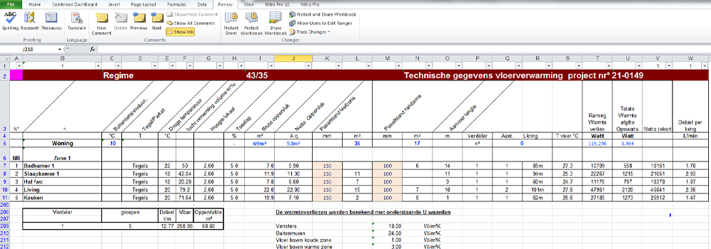
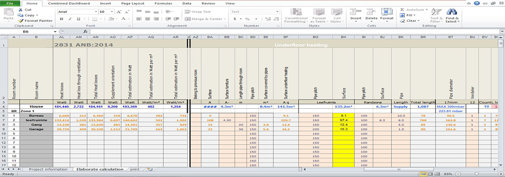
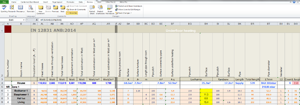
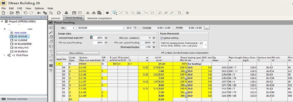
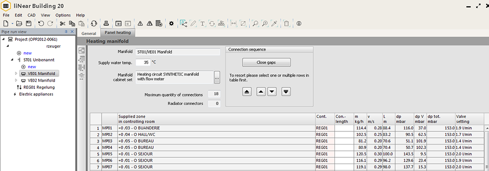
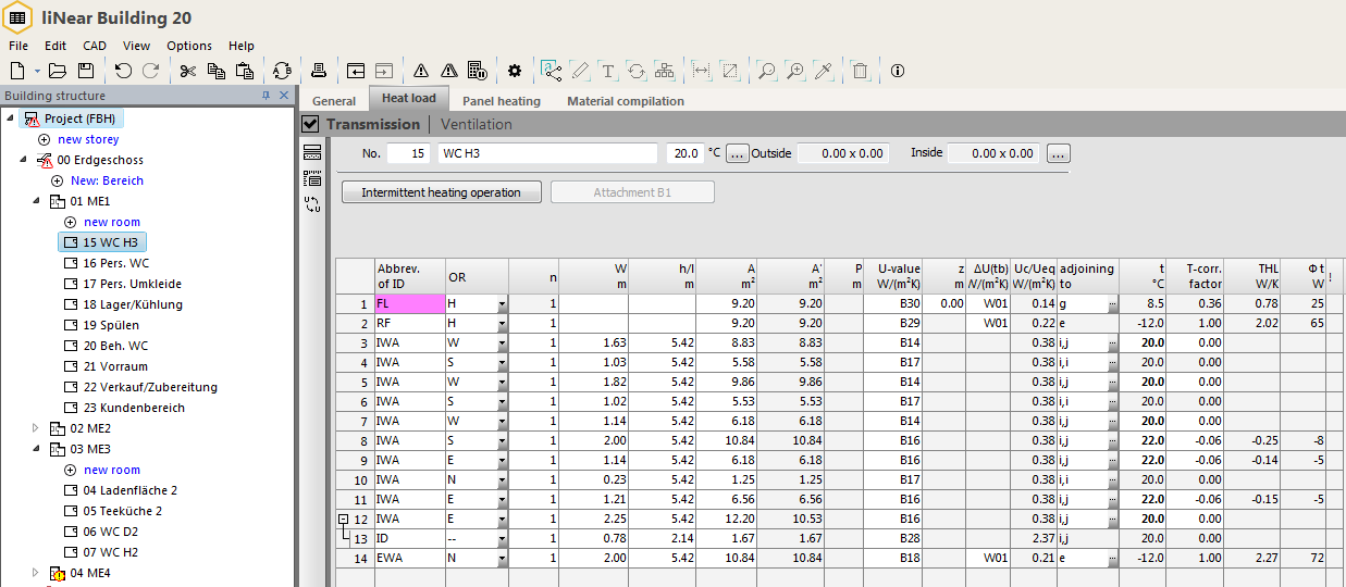
Heat Load calculation using liNear Building 20 program with AutoCAD 2016:
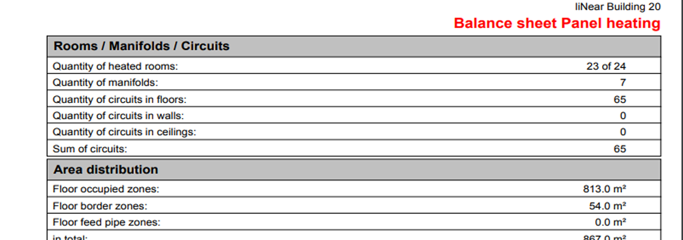
Quick calculation using liNear Building 20 program:
THINGS THAT SHOULD BE CONSIDERED
MANIFOLD Another consideration at the planning stage is the location of the UFH manifold. If the project includes several rooms, it is best to locate the manifold centrally between all the rooms that are being heated. We also recommend hanging the manifold a minimum of 250mm from the finished floor level to ensure easy access.
TYPE OF PIPE When it comes to wet underfloor heating it is best to use pipework that is specifically designed to be used for underfloor heating. The UFH pipe should dissipate heat quickly and evenly rather than act as an insulator, which is what some plumbing pipes are designed for.
PIPE SPACING The most common spacing between each pipe run is 200mm. However, this will vary in some instances both wider and narrower spacing, based on the heat loss of the area. Heat loss will be adversely affected by large areas of glazing, or poor insulation values.
PIPE LOOP LENGTH The length of each pipework loop is limited, i.e. you cannot just run a continuous loop! This is so that the pumped pressure and the water temperature is maintained throughout the pipework coil.
HEATING CONTROL/THERMOSTAT It is important that the proposed heating control areas are taken into account with the UFH design so that the pipework layout facilitates the required zoning.
ROOM LAYOUT the location of appliances such as toilets or kitchen units (if food products are stored within them) should be considered as typically UFH pipework should not run under them. We also recommend not running UFH pipework under shower trays, as this can cause the water in the shower trap to smell.
FLOOR COVERING Before installing underfloor heating it is vital the floor covering is considered as some floor coverings work better with underfloor heating than others. The resistance rating (normally measured in ‘TOG’) is taken into account on the UFH design, to make sure that the heat output will still be adequate, taking this resistance into account.
FLOOR CONSTRUCTION The floor construction will dictate which underfloor heating system is best suited to the project.
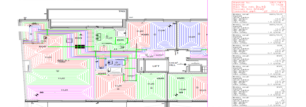
Drafting Using liNear
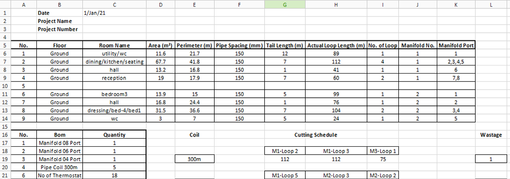
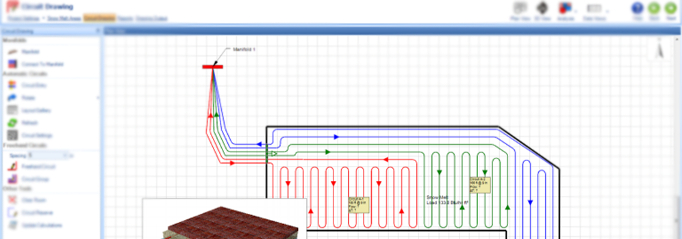
We provide drafting of underfloor heating network in liNear CAD 20. After the quick calculation and heat load calculation is done the information is extracted and being transferred to liNear CAD for drafting of the underfloor network. This is done using AutoCAD with liNear CAD. The liNear CAD output is quite detailed and carries all important information to be used by the client for laying purpose.
It includes manifold location and other details in the drawing. All heating circuit details like number, pipe distance, pipe length etc. were included in the drafting part.
Tenderings or Quotations
InfoTech provides tender quotation services to its customers which leads to meaningful price comparison list.
The tender quotation can also be provided (upon request) using liNear Quote – an ideal instrument for tendering.